Central sterile services department
General Planning Considerations
Sterilisation department in a hospital
The sterilisation department in a hospital is known by many acronyms, e.g.:
CSD Central Sterilisation Department
CPD Central Processing Area
SSD Sterile Service Department
TSSD Theatre Sterile Service Department
TSSU Theatre Sterile Service Unit
CSSD Central Sterile Service Department (the most widely used term in the South African context)
Location and functional relationship
Functional relationships to other departments
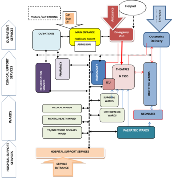
See Figure 1. The CSSD should be centrally located with ready access to all related service areas, such as the ICU, in-patient units and emergency unit. The department should also have direct access, either horizontally or vertically, to the operating theatres.
Deliveries and transportation routes
Trolleys are used as mode of transport for both receivables and deliveries. In order to cater for the high volume of trolleys to and from the CSSD receiving and dispatch areas, the entry/exit points should ideally be separated to create a uni-directional traffic flow and also to avoid cross-contamination through the division of the clean and dirty material.
Access for plant and equipment maintenance
Plant and equipment in service areas would need access from outside the CSSD, in order not to compromise the desired level of cleanliness in the unit. In some situations direct access between the plant area and the steriliser is required in order to allow access for maintenance staff to the equipment controls in the CSSD area side.
Primary function of a CSSD
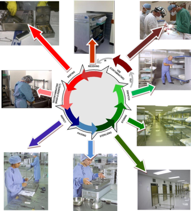
The primary function of a CSSD is to provide an efficient, economic, continuous and quality supply of sterilised items, when needed, to all patient-care service points in the hospital, and to receive returned contaminated items for cleaning. This process is generally referred to as the “decontamination life cycle” (see Figure 2).
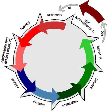
Activities in a CSSD can functionally be sorted under the following primary zones:
- Dirty Decontamination Zone
- Clean IAP (Inspection and Packing Zone)
- Sterile Clean Zone
In addition to the above primary zones, supporting activities are accommodated in the CSSD.
Support zone
In order to identify the functional relationship between the various spaces, the convention is used throughout this guide to indicate the respective zones in the following colours:
In order to create a work space for maintaining a clean environment suitable for handling sterile articles, access to the red, blue and green zones is restricted and subjected to “red-line” principle.
In addition to the above, the red area (decontamination zone) is divided with a hard barrier from the IAP area, in order to prevent contaminated particles from freely entering the relatively cleaner IAP area. This barrier could be a solid brick wall, or glass wall.
Activities comprising the decontamination cycle should allow a progressive work-flow pattern that commences with a “dirty” entry and receiving area, proceeds to a cleaning, decontamination and drying area, into a sorting and packing area, through to sterilisation and cooling area, to finish with sterile storage, distribution and exit areas.

Activities in a CSSD
The main activities of the “decontamination life cycle” taking place in a CSSD can be listed as follows:
- receiving of soiled (and contaminated) returns
- cleaning of trolleys
- sorting returned trays
- sorting, disassembling, cleaning and drying of all returned medical devices
- checking functionality and cleanliness of cleaned medical devices
- assembling, packing and wrapping of trays
- sterilisation
- cooling of sterile packs
- storage of sterilised items
- dispatching of orders
- quality control
- maintenance
- record keeping
- receiving new supplies.
These activities can be classified under the following functional areas:
Decontamination
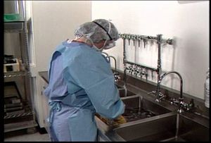
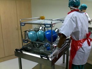
Decontamination involves the use of automated and manual cleaning to remove harmful blood-borne pathogens on the surfaces of equipment and instruments. Soiled items for re-use (medical devices, textiles and equipment) are received in the sterilising department after use in the various clinical departments. These could be operating theatres, emergency department and various wards. Medical devices, equipment and other contaminated articles will be sorted, disassembled, pre-rinsed and cleaned in the decontamination/dirty area. Used linen is put into linen bags and sent to the laundry. Waste items are sorted into suitable containers, according to policy, for appropriate disposal methods.
If items are heavily soiled a manual washing procedure will precede the automated cleaning process by washer-disinfectors. For manual cleaning, a double- (two-) sink arrangement is optimal, one for cleaning and one for rinsing. Automated washers or washer-disinfectors can be provided as single or double-door designs (the latter to allow for physical separation of the dirty and clean areas of the decontamination area).
Inspection
Decontaminated medical devices and equipment are visually inspected for functionality, damage and cleanliness according to required standards, the manufacturer’s instructions and written protocols.
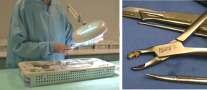
Packing
Decontaminated instruments, equipment and other articles are sorted, assembled, counted and packed prior to sterilizing.
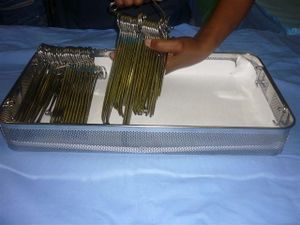
Sterilisation
Sterilisation is a defined process used to render a surface or product free from viable organisms, including bacterial spores. Depending on the product this procedure could vary from steam sterilisation, dry heat sterilisation, to low temperature sterilising processes.
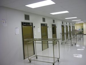
Storage
Sterile items are stored in a clean controlled environment to prevent re-contamination before use.
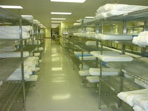
Functional Requirements
Activity zones in a typical CSSD
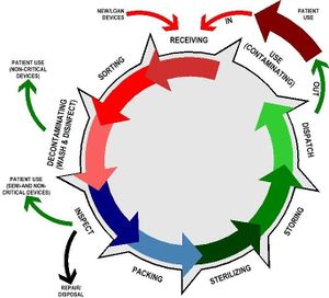
Figure 5 above is a variation of the generic ‘decontamination life cycle’, indicating the various dispatch points in the cycle.
Based on this principle, the activity spaces in a CSSD could be organised as per figure 6
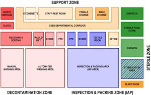
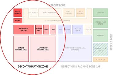
Decontamination zone
- Receiving and sorting
- Waste disposal
- Cleaner/sluice
- Trolley wash
- Manual cleaning
- Automated cleaning
- Raw materials and chemicals storage
- PPE area (gowning).
Inspection and packing zone (IAP Zone)
- Inspection and packing (IAP)
- Sterile pack
- Textile folding
- Raw materials storage
- PPE area (gowning).
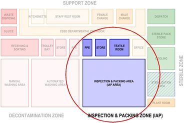
Sterile zone
- Sterilisation
- Cooling
- Sterile pack storage
- Dispatch.
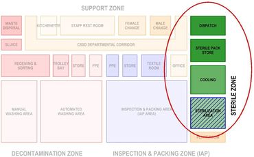
Support zone
- Office
- Staff rest room
- Kitchenette
- Female change room
- Male change room
- Manager’s office
- Steriliser plant room.
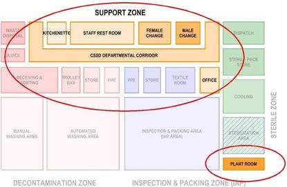
Functional relationship between activity spaces

Workflow
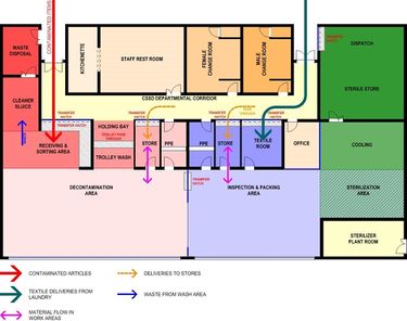
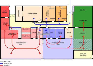
Design solutions should follow work-flow principles, separating dirty and clean areas. The workspaces in the decontamination and clean areas should be designed as open-plan work areas subdivided by benches and/or equipment into functional work areas. These work areas should be arranged to allow for a progressive work flow that commences with a ‘dirty’ entry and receiving area, proceeding to a cleaning, decontamination and drying area, into a sorting and packing area, through to a sterilisation- and cooling area, with sterile storage, distribution and exit areas completing the process.
It is critical to the functional efficiency and safety of the CSSD that these spaces are sequentially linked for one-way flow-through of instrumentation. The separation between the dirty area, where soiled goods are collected, and the clean area where washed and disinfected instruments are inspected, sorted and packed, is realised by a high throughput pass-through washer disinfector barrier.
Treated instruments are unloaded and managed directly in the clean packing area by different staff.
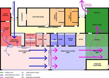
Material flow
Personnel flow
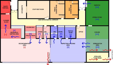
Air flow
General design considerations
Design for infection control
The design of a CSSD plays an essential role in addressing infection control issues to minimise the risk of infection transmission.
Planning and design features to support infection control should include the following:
- Restricted/controlled access
- Unidirectional work flow, progressing from dirty to clean to sterile areas
- Controlled air flow with positive air pressure from clean to dirty areas
- Containment of steam and moisture, preventing potential contamination of stored sterile articles.
- Building and layout details that would facilitate easy cleaning
- Selection of suitable building materials and finishes
- Selection of fixtures, fittings and equipment with suitable detail, materials and finishes for easy cleaning, and prevention of build-up of harmful organisms
- Adequate facilities for cleaning and waste management
- Access to the area should be limited and controlled. This should prevent any unauthorised person from entering the area without permission
- Staff/visitors should have access to hand-washing facilities, separate from those used for cleaning devices, before entering or leaving the areas.
- The flow of both staff and equipment must allow no cross-over of soiled and clean materials
- The operating procedure for infection control in a CSSD falls outside the scope of this guideline.
Design for Occupational, Health and Safety
Planning and design features to support occupational health and safety include the following:
- Selection of floor finishes with a non-slip finish
- Selection of fixtures, fittings and equipment with suitable detail, materials and finishes to prevent personal injury through accidents or misuse
- Provision of suitable and adequate facilities to support and encourage a high level of personal hygiene, with special reference to hand hygiene
- Provision of adequate dispensing points for the appropriate personal protection items (PPE) for the specific area to enable strict enforcement of PPE requirements in the protection of healthcare workers, especially as preventive measures against HIV aids
- Top-loading, worktop equipment should be accessible to staff members of all heights
- Ill-considered dimensions and layouts of fixtures and fittings could have a significant negative effect on occupational health and safety of staff.
As the requirements of the Occupational Health and Safety Act will apply, this section needs to be read in conjunction with the OHS-related guidelines.
Design for change and technology
Although it is difficult to predict future trends in CSSD technology, it is advisable to allow some flexibility and adaptability in space requirements, electrical consumption and layout, and also in air-handling capacity. Current trends that need to be considered are the following:
- The increasing complexity of surgical procedures requires more intricate equipment and instruments that need specialised care and handling during the sterilisation procedure
- Integrated computerised tracking facilities have become widely used and have become an essential tool in the validation of the sterilisation process
- Changing staff-flow patterns due to changing work-flow patterns as a result of procedural and/or equipment innovations
- Design towards sustainable architecture, i.e. water-saving equipment, and equipment with reduced toxic emissions. Constant improvements and innovations lead to products that run more economically and reach a higher level of environment compatibility
- The facility should be able to reasonably accommodate access and positioning of possible outsize equipment. Consideration for this possibility should be given from (and including) point of delivery to point of positioning
- It is advisable to allow capacity for extra machinery in the event of increased production demand.
Ergonomic and user-comfort considerations
Sterile services departments should be designed to protect staff from avoidable risks of injury. Badly designed elements such as height, depth and design of workstations and counters, shelving and the layout have an impact on the occupational health and safety of staff. Workspaces should therefore be sufficiently flexible and adaptable to accommodate adequate working space for individual comfort, and to reduce any unnecessary physical stress or risk of injury to the body from any repetitive and/or periodic actions such as lifting, pulling, pushing, etc.
Ergonomics considers the understanding of human-equipment interaction and design to minimise safety risks and achieve the optimum use of equipment. When particular high risks are identified, these should be minimised when designing the facility – while providing good lighting (preferably natural light), adequate ventilation, plenty of space, and comfortable humidity/temperature conditions. Workbenches and chairs must be height-adjustable, allowing staff to adopt the correct posture when sitting or standing.
Enough space must be available to allow for organisation of the workspace. All materials, for example those in the packing area, should be located within easy reach of the workbench (packaging materials, indicators, etc.). A similar concept should apply to device-sorting or manual-cleaning areas. There should be adequate space to manoeuvre, queue, and unload trolleys or other means of transportation. This will allow not only for good ergonomics but also for efficient work practices.
The provision of a pleasant interior environment can contribute to staff morale. Temperature and humidity control (air-conditioning), in particular in areas where heat-associated equipment (such as steam sterilisers and thermal washer-disinfectors) is used, is preferred. Provision must be made for adequate heat extraction systems from heat generating equipment such as autoclaves and instrument washers. This should be done as close to the source as possible i.e. above autoclave doors and instrument washers. This heat source can be utilized to pre-heat water going to the boilers. Consideration should also be given to ensure there is adequate lighting (preferably natural) and noise control.
For larger facilities, provision may need to be made for managers’ offices, general staff areas (for eating and drinking) and storage areas that are separated from the decontamination area. Good interior design also contributes to staff morale. The aim should therefore be to create an attractive and cheerful environment throughout the department.
Sound
Noise must be controlled
- A threshold of 60dBA (decibel) must not be exceeded
- The walls and ceilings should be made of absorbent materials so that they do not reflect sound
- Insulation of sterilisers and washer-disinfectors in technical walls will reduce the noise level
- Offices should allow confidential discussions to take place in privacy, away from noisy mechanical or high-volume human areas.
Natural light
Natural lighting is highly desirable, especially in the work areas, and should be used wherever possible, especially in areas such as the cleaning and packing areas. However, direct sunlight on work spaces should be avoided.
Natural ventilation
Natural ventilation through opening-section windows should be limited to offices and staff rooms. However, this is not recommended as it could promote contamination of the internal space by outside sources. Mechanical ventilation should be provided through the remainder of the CSSD, with good primary and secondary filters which must be monitored with differential manometers linked to an alarm system.
Communication
Provision must be made for communication systems to minimise the passage of staff to and from the clean zone. Glass partitions, communication panels, IT and video links for data transfer, intercom and telephones can serve as appropriate means of communication.
Glass partitions should be used to permit observance of the activities within the clean zone (from the outside) without having to enter it. The glass panels must be of a non-opening design and must be waterproof and flush-mounted.
CSSD Area Determination
Determination of size and layout
The size of a CSSD in a hospital is unique to that hospital, as the size, layout and function of a CSSD are defined in the Operational Policy Statement that guides the operational management of the hospital. The operational policies specific to the CSSD precede sketch design stage. These policies are developed by the project team in consultation with health; service stakeholders, who should have the knowledge and experience to analyse the various processes in and related to the CSSD.
These operational policies define the “What, How, When, Where, Who and With What” of any activity and/or process and are major space determinants which could significantly affect the planning and design of the CSSD, as they can have an impact on the size, configuration and the nature of accommodation. Operational policies will vary from unit to unit depending on a wide range of factors, both external and internal to the CSSD.
Determining factors external to the CSSD
Examples of these space determinants could include the following:
- number of theatres/case mix
- surgical procedures
- extent of storage in the theatres and wards
- distribution system that will be used (vertical, horizontal, trolleys, lifts)
- amount of space needed for waste management
- processing needs for re-usable textiles (receiving, transporting, collecting, storing)
- staff facilities to be shared with adjacent departments. See annexure A for a generic set of Standard Operating Policies (SOP) for a typical sterile service department.
Determining factors internal to the CSSD
Examples of these space determinants could include the following:
- types of processing equipment to be used (washer, washer-disinfectors, single- or multi-chamber washers, ultrasonic cleaners, endoscope processors)
- types of packaging to be used (disposable wraps and pouches, re-usable wraps, rigid containers
- echnology to be used for sterilisation (high temperature or low temperature sterilisation, other chemical sterilants, steam)
- anticipated inventory storage
- anticipated volume of consumable supplies
- type of documentation and record-keeping system to be used (manual vs computerised)
- instrument inventory
- equipment inventory
- projected workload
- staffing structure – number of offices
- staffing policy - number of staff to be accommodated
- types of cleaning equipment selected such as multi chamber or single chamber
- number of sterilisers and whether front or double sided loading
- emergency sterilisation requirements.
CSSD area determination
Hoët (1989 cited in AFS Working Group, 2008b, p.281) has estimated the following ratios as a broadbased calculation of CSSD space:
- 0.7 m²/bed from 0 to 300 beds
- 0.6 m²/bed from 300 to 600 beds
- 0.5 m²/bed for more than 600 beds.
Based on these ratios, the following table can be compiled:
Table 2:Ratio of hospital bed to CSSD area
| BED SIZE | CALCULATION | SURFACE AREA |
| 200 BEDS | 0.7 m² /bed | 210 m² |
| 400 BEDS | 0.6 m² /bed | 240 m² |
| 600 BEDS | 0.5 m² /bed | 300 m² |
| 800 BEDS | 0.5 m² /bed | 400 m² |
| 1000 BEDS | 0.5 m² /bed | 500 m² |
| 1200 BEDS | 0.5 m² /bed | 600 m² |
AFS Working Group (2008b, p.291) states that the CSSD has few internal corridors, the commonly used net to department functional factor adopted is 1.30. The 1.30 factor anticipates that the internal circulation must be added to connect functional areas and individual rooms. This minimal surface area required can be estimated as being 200m² useful and 260m² net floor areas.
Based on the above assumption, AFS Working Group (2008b, p.291) calculates the useful surface area using the MSO ratio based on the number of beds used for Medical – Surgery – Obstetrics (MSO), using the following calculation basis:
Table 3: Ratio of MSO to CSSD area
| MSO – NR OF BEDS | USEFUL SURFACE AREA/BED | USEFUL SURFACE AREA | NET SURFACE AREA |
| < 200 BEDS | 200 | 200 m² | 260 m² |
| 200 – 300 BEDS | 1,5 m² /bed | 300 – 400 m² | 400 - 520 m² |
| 300 – 400 BEDS | 1,2 m² /bed | 350 – 420 m² | 450 – 550 m² |
| 450 + BEDS | 1,0 m² /bed | 450 m² | 600 m² |
Studies done by Putsep and Cowan (1983, p.8) produced the following ratios depending on the ‘active’ nature of the bed.
Table 4: Comparative recommendations for estimating the size of a CSSD (Putsep and Cowan,1983, p.8)
| NR OF
BEDS |
SCANDINAVIA | BELGIUM | NETHERLANDS | RSA1 |
| m² PER BED | ||||
| 200 BEDS | 1,1 m² /bed | 0,6 - 1 m² /bed | 0,7 m² /bed | 1,0 m² /bed23 |
| 350 BEDS | 1,1 m² /bed | 0,6 - 1 m² /bed | 0,6 m² /bed | 1,0 m² /bed |
| 500 BEDS | 1,1 m² /bed | 0,6 - 1 m² /bed | 0,5 m² /bed | 1,0 m² /bed |
| 750 BEDS | 1,1 m² /bed | 0,6 - 1 m² /bed | 0,4 m² /bed | 1,0 m² /bed |
Based on the above data, the areas are as follows:
| NR OF
BEDS |
SCANDINAVIA | BELGIUM | NETHERLANDS | RSA3 |
| TOTAL AREA | ||||
| 200 BEDS | 220 m² | 160 m²*4 | 140 m² | 200 m² |
| 350 BEDS | 385 m² | 280 m² * | 210 m² | 350 m² |
| 500 BEDS | 550 m² | 400 m² * | 250 m² | 500 m² |
| 750 BEDS | 825 m² | 600 m² * | 300 m² | 750 m² |
As the schedules of accommodation on which the above analyses are based have not been included in the study, the equitability of the comparisons is in doubt.
It is however; clear that the size of a CSSD cannot be generically determined on the basis of statistics or averages. Every CSSD has its own set of area determinants that need to be logically evaluated in order to arrive at an area that is the optimal combination of functionality and cost effectiveness.
Proportional allocation of space in a CSSD facility
Table 5: Space allocation in a CSSD (Putsep and Cowan,1983, p.9)
| AREA | NUFFIELD
PROVINCIAL HOSPITALS TRUST (1963) |
ESTIMATED
AVERAGE – SWEDISH PRACTICE |
NORWEGIAN
RECOMMENDATIONS (1978) |
HOET
(1981) |
| RECEIVING
WASHING DECONTAMINATION |
10 | 19 | 10 | 30 |
| CLEAN AREA | 35 | 20 | 25 | 30 |
| STERILISATION AREA | 5 | 8 | 5 | 25 |
| STERILE SUPPLY | ||||
| STORE DISPATCH | 16 | 29 | 25 | |
| BULK STORE | 11 | 14 | 20 | 15 |
| STAFF AREA
OFFICE HOUSEKEEPING |
23 | 10 | 15 |
AFS Working Group (2008b, p.291) states that the areas within the CSSD can be sub-divided as follows:
Receiving: 10% of the surface area
Decontamination: 25% of the surface area
| DIRTY 35%
| |
| CLEAN 35%
| |
| STERILE 20%
|
SUPPORT 10%
If the generic plan used as basis for this study (LAYOUT 2.1) is subjected to an area analysis, the following table can be compiled (TABLE 4.5) for an autonomous (support services not shared) CSSD of 600m². If staff facilities and corridors are shared with another department (e.g. theatre department), the CSSD’s size reduces to 450m² as per TABLE 4.6, illustrating the difficulty in achieving universally applicable areas, and the effect of hospital-specific policies.
It is significant that the percentage of total areas of TABLE 4.6 compares favourably with the AFS Working Group’s recommendations.
Table 6: Proportional space allocation - Generic layout (600M2 gross area)
| DIRTYCLEANSTERILE SUPPORT | ||||
| Area (m²) | Area (m²) | Area (m²) | Area (m²) | |
| WASTE DISPOSAL | 12 | |||
| SLUICE | 12 | |||
| RECEIVING & SORTING | 25 | |||
| TROLLEY WASH | 5 | |||
| TROLLEY HOLDING | 5 | |||
| STORE | 12 | |||
| PPE TO DECON AREA | 8 | |||
| DECONTAMINATION AREA | 100 | |||
| PPE TO IAP AREA | 8 | |||
| STORE | 12 | |||
| TEXTILE AREA | 16 | |||
| INSPECTION & PACKING | 100 | |||
| STERILIZATION | 30 | |||
| DISPATCH | 15 | |||
| STERILE STORE | 40 | |||
| COOLING | 30 | |||
| STERILIZER PLANT ROOM | 18 | |||
| OFFICE | 12 | |||
| KITCHENETTE | 12 | |||
| STAFF REST ROOM | 35 | |||
| FEMALE CHANGE | 30 | |||
| MALE CHANGE | 15 | |||
| CSSD CORRIDOR | 48 | |||
| TOTAL AREA (SQ M) | 179 | 166 | 85 | 170 |
| % OF TOTAL AREA | 30% | 28% | 14% | 28% |
Table 7: Proportional space allocation - Generic layout without staff facilities (450M2 gross area)
| DIRTY CLEAN STERILE SUPPORT | ||||
| Area (m²) | Area (m²) | Area (m²) | Area (m²) | |
| WASTE DISPOSAL | 12 | |||
| SLUICE | 12 | |||
| RECEIVING & SORTING | 25 | |||
| TROLLEY WASH | 5 | |||
| TROLLEY HOLDING | 5 | |||
| STORE | 12 | |||
| PPE TO DECON AREA | 8 | |||
| DECONTAMINATION AREA | 100 | |||
| PPE TO IAP AREA | 8 | |||
| STORE | 12 | |||
| TEXTILE AREA | 16 | |||
| INSPECTION & PACKING | 100 | |||
| STERILIZATION | 30 | |||
| DISPATCH | 15 | |||
| STERILE STORE | 40 | |||
| COOLING | 30 | |||
| STERILIZER PLANT ROOM | 18 | |||
| OFFICE | 12 | |||
| TOTAL AREA (SQ M) | 179 | 166 | 85 | 30 |
| % OF TOTAL AREA | 39% | 36% | 18% | 7% |
Typical Floor Layouts
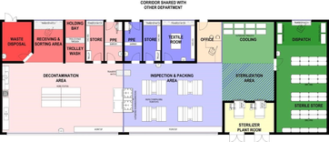
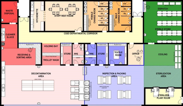
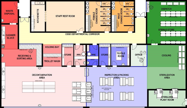
The following generic plans are included to illustrate the combined effect of gross floor area allocation, proportional space allocation, and work-flow requirements.
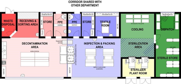
Proportional Net space allocation
| DIRTY | 37% |
| CLEAN | 36% |
| STERILE | 21% |
| SUPPORT | 6% |
Proportional Net space allocation
| DIRTY | 38% |
| CLEAN | 33% |
| STERILE | 22% |
| SUPPORT | 7% |
Proportional Net space allocation
| DIRTY | 30% |
| CLEAN | 28% |
| STERILE | 14% |
| SUPPORT | 28% |
Individual Space Requirements
CSSD Layout Unpacked
Due to the uni-directional sequential nature of the work flow in the CSSD, activities are interrelated and inter-dependent. It is, therefore, critical to the functional efficiency and safety of the CSSD that those areas are sequentially linked for uni-directional flow-through of instrumentation, with no room for back tracking.
The above work flow and interrelationship between the adjacent areas dictates the characteristics of each space. In order to discuss each area individually, it is necessary to have a base plan as a reference point. The typical floor layout based on a 600m2 unit will be used for this purpose.
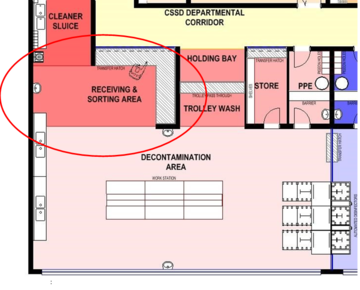
Receiving and Sorting
Function
This is the area where all soiled articles for reprocessing are received on trolleys from the main corridor from user departments throughout the hospital.
Location and Relationship
- Close to main entry doors to the CSSD unit
- Visual access to main entry.
Activities
- Access for deliveries of supplies, return of contaminated goods and the collection of waste and contaminated linen
- Contaminated articles are received at a counter with a trolley hatch, where the articles are logged, sorted and forwarded to the decontamination area
- Contaminated linen is put into linen bags and stored in the waste-disposal store for transport to the laundry
- Supplies are received in the supplies store where they are opened and packaging is discarded in the waste-disposal store
- Trolleys are sent to the trolley wash bay.
Requirements
- Visual access to entrance doors
- All entrances should be secure and controlled by means of communication to prevent access by unauthorised people
- A glass partition with lockable sliding hatch between this area and the corridor • A lockable hatch for trolleys
- The red-line principle is applicable at the receiving area; only material and trolleys are to enter the CSSD via this entrance • Worktop for unpacking and sorting
- Hand-washing facilities.
Fixtures, fittings and equipment
- Receiving counter with pass-through hatch and trolley hatch, acting as red line
- Sorting work tables – standing height
- Clinical hand-wash basin, complete with liquid soap dispenser and paper-towel dispenser • Space should be allowed for record-keeping and record-keeping supplies.
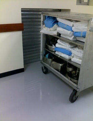
Services
- 2 x telephones
- 2 x data points
- CSSD technician call system
- Power outlets for computer points, computer, fax and printer
- Access control to outside door.
Waste Disposal
Function
Contaminated waste articles are stored for collection and transport to the respective disposal areas.
Location and relationship
Attached to the receiving area.
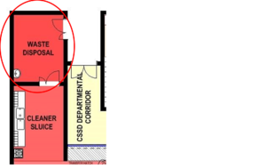
Activities
- The sluice area and waste-disposal area could be combined in smaller units
- Contaminated waste articles are temporarily stored for collection and transport to the respective disposal areas
- Contaminated linen is temporarily stored in canvas bags for collection and transport to the laundry
- Third-party collection area (depot).
Categories of waste stored in the waste-disposal area could include:
- Health-care waste, infectious waste, sharps
- General office waste
- Packaging and cartons from bulk supplies stored in the unit • Linen bags used to collect reusable items
- Sharps from theatres.
Requirements
- An independent secure area for temporary storage of clinical waste awaiting collection in accordance with local waste management policy
- The door to the receiving/sorting area side should be lockable from the CSSD side to prevent unauthorised entry
- Room layout should allow for easy recycling/re-use/disposal policy
- Space for linen bags and waste containers
- An impermeable, hard-wearing floor with good drainage; it should be easy to clean and to disinfect, with an accessible water supply for cleaning purposes
- The area should be protected from outside elements, inaccessible to animals, insects or birds and not situated in close proximity to fresh food stores, food preparation areas or patient waiting areas
- It should be sized according to the volume of waste generated by the facility as well as the frequency of collection.
- A bumper rail to protect the wall behind the trolleys • Containers according to waste policy.
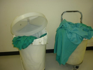
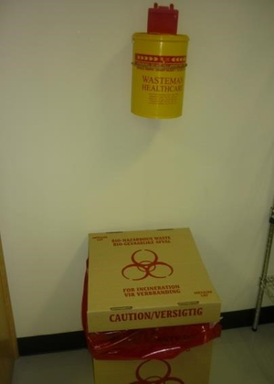
Fixtures, fittings and equipment
• Clinical hand-wash basin, complete with liquid-soap dispenser and paper-towel dispenser.
Sluice
Function
Heavily soiled items are rinsed and waste items are discarded in suitable containers.
Location and relationship
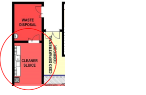
Activities
- Cleaning of heavily soiled items
- Storing and cleaning of domestic cleaning equipment and holders (buckets, etc.).
Requirements
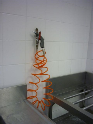
- Some lumens may require irrigating with a high pressure water-jet spray gun
- Heavily soiled instruments should be pre-rinsed using a submerged high-pressure water gun in a sluice area.
Fixtures, fittings and equipment
- Above-sink storage facilities for cleaning material and equipment
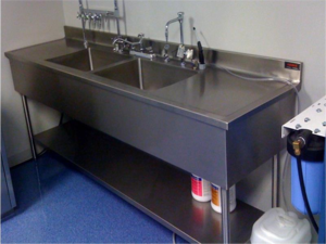
- Sluice unit
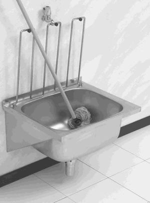
- Bucket sink
- Mop/broom rail.
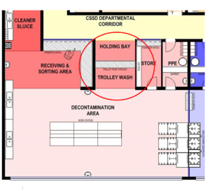
Trolley wash and storage
Function
Area for washing, disinfecting and storing of trolleys.
Location and relationship
Activities
- This area receives returned contaminated trolleys from the decontamination area
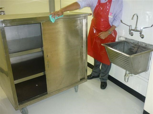
- Trolleys are washed and cleaned before being moved through a trolley hatch to the holding bay
- Washed trolleys are temporarily stored in the holding bay until required.
Requirements
- Trolleys must be transferred via a trolley hatch to prevent entry
- The floor in the washing bay needs to have a gradient and floor drain, as well as hosing facilities
- Trolley-washing facilities with adequate drainage.
Fixtures, fittings and equipment
- Trolley pass-through hatch
- Stainless steel sink • Water hose with hand-spray.

Services
- Cold water for water hose
- Floor drain in vicinity of wash stations and equipment loading/unloading areas.
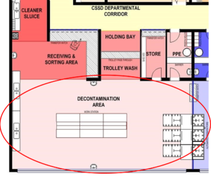
Decontamination Area
Function
This area is used to sort instruments followed by manual or automated cleaning.
Soiled instruments are placed in a pass through washer disinfector that will deliver clean instrumentation to the IAP Area. Selected items may be manually cleaned, because they are either too delicate or will not fit into the washer disinfector, then forwarded to the clean area via a pass-through hatch.
Activities
- Selective manual cleaning of instruments and equipment not suitable for automated cleaning.
- Disassembly and inspecting of contaminated returns
- Rinsing of instruments and equipment
- Sorting and loading of medical instruments and equipment into trays/washer-disinfectors and other automated cleaning equipment.
Requirements
- Sufficient wall-mounted brackets for cleaning chemicals and brushes
- Sealed closed windows to the outside would be desirable
- Space to park trolleys is essential
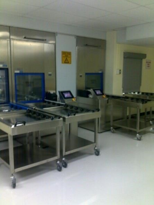
- Automated double-sided washer-disinfectors and ultrasonic cleaners are required for cleaning and drying of all suitable instruments and equipment. A minimum of two washing units should be provided to allow for maintenance and down-time
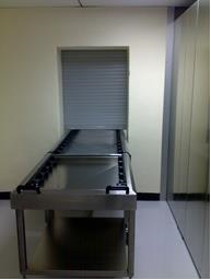
- Transfer hatch with sliding opening section (upwards or sideways) for the transfer of handwashed items and return of emptied disinfector trays
- The decontamination area has to be divided with a hard barrier from the IAP area, in order to prevent contaminated particles from freely entering the relatively cleaner IAP area. This barrier could be a solid brick wall or washer-disinfectors with panelling. A glass partitioning will contribute to an open-plan environment
- Adequate space should be allowed for trolleys to be manoeuvred without interfering with the work stations
- The distance between tables should be about 1.5m and between a table and the wall not less than 1,2m.
Fixtures, fittings and equipment
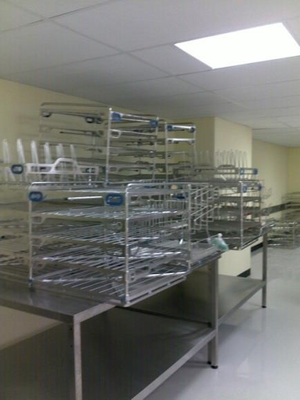
- Stainless steel standing-height sorting tables with high-level shelves
- Ultrasonic cleaner, according to service requirements
- Washer-disinfectors with a drying cycle for instruments and tubing, according to service requirements
- De-ionised, distilled, or reverse osmosis (RO) water for final rinsing is preferable
- Drying rack - work space must be available for drying manually cleaned instruments
- Double-bowl stainless steel pot-wash type sink with draining boards on both sides
- Tubing manifolds (air and water) and additional water outlets for water pistols
- A 1000mm-long flexible hose with a tapered-nozzle water pistol for cleaning narrow-bore tubes should be fitted over the space between the bowls
- All taps to sinks should have threaded nozzles to allow for the fitting of a variety of cleaning gadgets
- Compressed-air outlets and pressure guns are required at all cleaning sinks
- Clinical hand-wash basin, complete with liquid-soap dispenser and paper-towel dispenser
- Wall-mounted cartridge soap dispenser
- Eye wash and first aid area
- Automated washer disinfectors with a choice of racks for respiratory equipment washer, bowls, basins, containers, etc.
- Transfer trolleys
- Waste container for non-regulated waste and sharps
- One height-adjustable chair per table
- A silent clock • Storage shelving.
Services
- Services to automated disinfectors as per manufacturers’ specifications
- Floor drains
- Trap for equipment drainage.
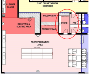
Raw materials and chemicals store
Function
Storage of consumables, raw goods and materials, and chemicals used in the decontaminated area.
Location and relationship
Activities
- Receiving and storing of raw materials and consumables
- Distribution of goods to process areas
- Facilitating the disposal of transport packaging
- Storage of consumables, raw goods and materials, and chemicals used in the decontaminated area.
Requirements
- Lockable transfer hatch on top of a worktop between this area and the department corridor
- Suitable slatted shelving for the range of consumables and chemicals that are stored in this room • Space for receipt, quarantine, inspection and acceptance of materials
- The store should be lockable.
Fixtures, fittings and equipment
- Slatted shelving
- Transfer hatch.
PPE Area - Gowning (to contaminated area)
Function
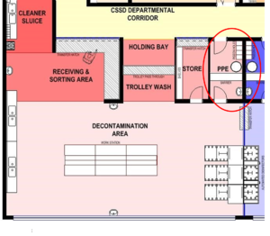
The PPE (personal protective equipment - gowning) room provides the only access to and from the decontamination area for staff, after putting on the appropriate PPE over garments and footwear.
Location and relationship
The PPE room is the only human entry/exit point between the decontamination area and the CSSD departmental corridor.
Activities
- The PPE gowning room provides the only access to and from the decontamination area for staff.
- Facilities are provided for the storage and dispensing of personal protective equipment (PPE) over garments and footwear suitable for the decontamination-room activities
- It provides facilities for hand-washing before/after activities in the decontamination area
- The PPE area serves as transfer point into/out of the red-line area.
Requirements
- PPE dispensers.
- Red-line demarcation barrier, with step-over wall
- There should be vision panels in doors and walls.
Fixtures, fittings and equipment
- Shelving for PPE dispensers
- Footwear and over-garment storage
- Waste containers – either foot-operated or wall-mounted
- Clinical hand-wash basin complete with liquid-soap dispenser, paper \-towel dispenser, and mirror.
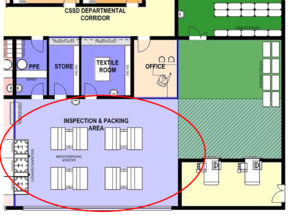
Inspection and packing area (IAP Area)
Function
Decontaminated instruments, equipment and other articles are inspected and packed here.
Location and relationship
The IAP area must be divided by a hard barrier from the decontamination area, in order to prevent crosscontamination. This barrier could be a solid brick wall or built in washer-disinfector with panelling, but a glass wall will contribute to an open-plan environment.
Activities
- Inspecting, functionality testing, assembling and packing cleaned and disinfected medical devices and accessories, according to predetermined required standards, in preparation for sterilisation
- Packs are checked, reassembled, double-wrapped, labelled, dated, and signed on the checklist by the packer
- Delivering items to the steriliser loading area • Returning racks to the decontamination area.
Requirements
- Sufficient wall-mounted brackets for equipment
- Sealed closed windows to the outside would be desirable
- Space to park trolleys is essential
- Automated double-sided washer-disinfectors and ultrasonic cleaners are required
- Transfer hatch with sliding opening section (upwards or sideways) for the transfer of manually cleaned items, and return of empty washer racks
- The IAP area must be divided by a hard barrier from the decontamination area, in order to prevent cross-contamination
- Adequate space should be allowed for trolleys to manoeuvre without interfering with the work stations
- The distance between tables should be about 1.5m, and that between a table and the wall not less than 1.2m
- Packing tables require power and ICT connections for use with computers and instrument scanners
- Space for mobile shelving units containing the items awaiting packaging.
- Sterilisation wrap storage space/rack
- Hand rub station
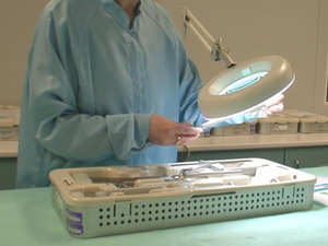
- Clean environment with good lighting for inspections • There should be vision panels in doors and walls.
Fixtures, fittings and equipment
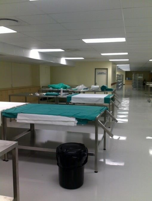
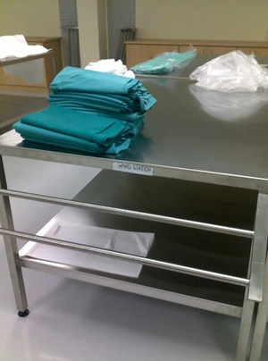
- Packing table(s) 2000mm x 700mm, by 800mm high, with a shelf below its surface and a basket rack above it
- Stainless-steel worktop space for a variety of activities
- Stainless-steel storage for raw materials
- High level storage for tray checklists
- Mobile, height-adjustable chairs/stools • Table mounted lighted magnifiers • Hand rub station.
Services
- Sufficient plug points for power to equipment on the packing tables should be ceiling-suspended
- Medical-grade compressed air.
Raw materials store for IAP Area
Function
Storing of materials used for processing in the clean side of the CSSD.
Location and relationship
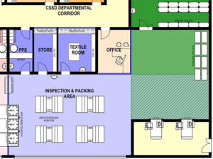
Activities
Storing of materials used for processing in the clean side of the CSSD.
Requirements
Lockable transfer hatch on top of a worktop between this area and the department corridor.
Suitable slatted shelving for the range of consumables and chemicals that are stored in this room.
Fixtures, fittings and equipment
- Slatted shelving
- Transfer hatch.
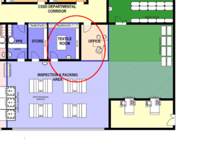
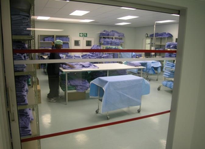
Textile room
Function
Receiving, folding, packing, and storing of textile materials.
Location and relationship
The textile room should be in close proximity to the IAP area, but also have a hatch to the CSSD departmental corridor to receive deliveries from the laundry.
Activities
- Due to linting, linen MUST be folded in a separate room with its own air-conditioning.
- Once laundered, ironed, checked and folded, clean unwrapped textiles should be handled as little as possible and be placed in a positive-pressure, temperature-controlled, and properly ventilated area with limited access in order to prevent accumulation of dust and lint.
Requirements
- Receiving hatch to departmental corridor side
- The area used for the textile preparation should be physically separated from all other areas
- The ventilation system should be designed so that air flows into the textile preparation area (via negative pressure)
- The air flow should be of a down-draft type, and the number of air exchanges per hour should be sufficient to minimise lint particles in the air
- Vision panels in doors and walls.
Fixtures, fittings and equipment
- Clinical hand-wash basin, complete with liquid-soap dispenser and paper-towel dispenser
- An illuminated linen inspection and folding table, 1800mm x 1250mm by 800mm high, with a foot switch to operate the light only during inspection. An acid-etched glass with the etched surface facing inwards would reduce the glare
- Shelving
- Stainless steel standing-height processing tables • Pass-through window.
Building services
Extraction with lint filter.
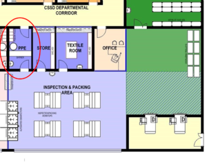
PPE Gowning area (to clean area)
Function
The PPE (gowning) room provides the only access to and from the decontamination area for staff, after putting on the appropriate PPE (personal protective equipment - over garments and footwear).
Location and relationship
The PPE room is the only human entry/exit point between the clean/IAP/steriliser/sterile storage area and the CSSD departmental corridor.
Activities
- The PPE (gowning) room provides the only access to and from the clean/IAP/steriliser/sterile storage area for staff
- Facilities are provided for the storage and dispensing of PPE (personal protective equipment - over garments and footwear) suitable for the decontamination room activities
- The room provides facilities for hand decontamination before/after activities in the clean (IAP) area
- It serves as transfer point into/out of the red-line area.
Requirements
- PPE dispensers.
- Red-line demarcation barrier, with step-over wall
- There should be vision panels in doors and walls.
Fixtures, fittings and equipment
- Shelving for PPE dispensers
- Footwear and over-garment storage
- Waste containers – either foot operated, or wall-mounted
- Clinical hand-wash basin, complete with liquid-soap dispenser, paper-towel dispenser and mirror.
Sterilisation area
Function
Area where loading trolleys are parked, sterilisers are loaded, sterilisation cycles are run, sterilisers are unloaded, sterilised packs are cooled, following completion of the sterilisation cycle. The size of the area will be dependent on the number and type of sterilisers installed and whether single- or double-door.
Location and relationship
- This area is the transition from clean to sterile area
- The sterilisation area should be adjacent to the preparation and packaging area.
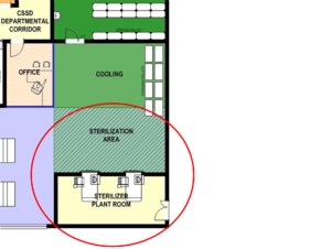
Activities
- Receiving packaged products from IAP
- A holding area for loaded and empty sterilisation trolleys
- Loading sterilisers
- Unloading single-door sterilisers
- Facilitating validation and routine testing of sterilisers
- Cooling of sterilised goods
- Where single-door autoclaves are installed, the autoclaves will be loaded and unloaded in the same area
- Where double-door autoclaves are installed, the unloading area is separate from the loading area
- In both cases, a separate cooling area from the loading area is required.
Requirements
- Sufficient sterilisers to meet hospital needs
- Preferably sterilisers should be located in a restricted access area
- Autoclaves should not be located in high-traffic areas or near any potential sources of contamination, wash sinks, or containers for the disposal of linen and trash
- Material should flow from the preparation and packaging area to the sterilisation area and then on to sterile storage or distribution
- The ventilation system should be designed so that air flows out of the sterilisation area (via positive pressure)
- Circulation space for the free and unhindered manoeuvring, loading and unloading of steriliser trolleys
- Exhaust over the front of the steriliser doors to extract heat and steam, in order not to compromise the HVAC air flow and temperature. An extraction system which is activated by the autoclave door opening rather than a constant extraction system should be considered
- It is generally advisable to install two smaller autoclaves rather than one large one
- An extra autoclave should be provided to cater for exceptional demand, maintenance and breakdown
- A clear space of 2m in front of the autoclave is needed to facilitate the handling of loading trolleys
- No partition wall should be closer than 750mm to any autoclave
- The autoclaves must be well insulated. The emission of heat to the environment must be minimal, and adequate extraction facilities should be provided to remove hot air and steam from the autoclave at a rate equivalent to 15 air changes per hour
- Require separate installation and accommodation according to manufacturer's recommendations
- The size of the area will be dependent on the number and type of sterilisers installed and, importantly, whether the sterilisers are single- or double-sided
- A duct enclosure can also minimise heat build-up within the workroom. An exhaust over the front of the steriliser(s) should be considered, to extract both heat (cabinet) and steam (opening door).
Fixtures, Fittings and Equipment
• Adequate space should be allowed for sterilisers and aerators; loading, cooling of autoclave racks, storage of long, heat-resistant gloves • Autoclave cleaning supplies.
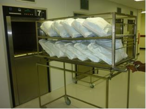
Cooling Area
Description and function
This area is used for the cooling of sterilised items on trolleys after being removed from the sterilisers.
The size of the area will be dependent on the number and type of sterilisers installed.
Location and relationship
This area is directly adjacent to the sterilisation area. Sterile items are temporarily stored here until cooled.
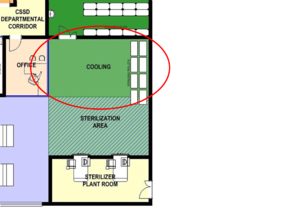
Activities
- Cooling of sterilised items
- Transferring cooled items to storage.
Requirements
- Sufficient space for trolleys to stand and manoeuvre until they have been cooled and inspected • This should be a clear open space with sufficient room to manoeuvre sterilising trolleys
- Demarcated bay – floor marking.
Sterile Stores
Description and function
A dedicated sterile storage and dispatch area.
Location and relationship
The sterile storage area should be located adjacent to the sterilisation area preferably in a separate, controlled, enclosed, limited-access area, the only function of which is to store sterile supplies.
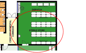
Activities
Storing of sterile packs.
Requirements
- Supply air pressure should be positive with respect to surrounding areas and the level of filtration should be equal to that in an operating theatre
- There should be vision panels in doors and walls
- Area to be protected from direct sunlight
- Adequate and appropriate stainless steel slatted shelving in a clean environment
- Adequate and appropriate mobile storage systems and trolleys.
Fixtures, fittings and equipment
- Closed or covered mobile storage systems are preferable for high-traffic areas
- Open or wire shelving is suitable for confined storage areas, provided that proper attention is given to traffic control, area ventilation, and housekeeping
- Hand rub station.
Dispatch Desk
Function
Distribution of sterile items to the various user departments.
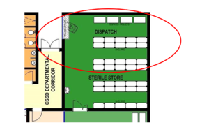
Activities
- Dispatch of sterile items to the theatres and wards
- Loading of sterile articles on trolleys
- Logging of dispatched deliveries.
Requirements
- Counter with service hatch and trolley pass-through hatch
- Red-line principle is applicable
- No general access is allowed into the sterile storage and dispatch area.
Fixtures, fittings and equipment
- Trolley pass-through hatch and counter hatch
- Clinical hand-wash basin, complete with liquid-soap dispenser and paper-towel dispenser
- Stainless steel shelving
- Filing cabinet
- Desk
- Chair
- Telephone
- Work surface
- Hand rub station.
Office
Function
A space for administration/management.
Location and relationship
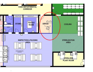
Activities
- Making and receiving phone calls
- Writing reports
- Access and printing data from computer
- Unit management
- Shift handover meetings
- Staff management
- Record keeping and storage.
Requirements
- The office should be lockable
- No direct access from this area to the work areas is allowed. This area can also have a hatch link to the main hospital passage so that suppliers can interact with the unit manager without coming into the unit. This would be an infection risk.
Fixtures, fittings and equipment
- Desk/sitting-height worktop
- Pinning board
- Whiteboard with marker tray
- Blinds for privacy
- Chairs
- Filing cabinet
- Shelving
- Filing cabinet
- Stationery cupboard.
Services
- IT and data connections
- Electrical points • Telephone point.
Kitchenette
Function
Preparation of light meals and refreshments.
Location and relationship
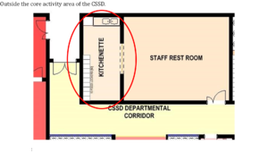
Activities
- Storing lunch packs
- Preparing light meals
- Making coffee/tea.
Requirements
Work surface, storage space, cupboards
Place for a fridge
Position for food trolleys from catering service.
Fixtures, fittings and equipment
- Standing-height worktop
- Standing-height double-end, double-bowl wash-up sink on fixed legs
- Fridge
- Microwave oven
- Toaster
- Storage cupboards
- Hydroboil.
Staff Rest Room
Function
- Space for staff to take tea and lunch breaks
- The space could also be used for staff meetings and training
- A minimum area of 15² is required, allowing 1.5m² per person. Size is dependent on the number of staff using the facility and the usage of the facility
- In district and regional hospitals, the staff room may also be used as a training area.
Location and relationship
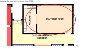
Activities
Eating
Relaxing
Informal meetings.
Requirements
Area for relaxing.
Fixtures, fittings and equipment
- Desk/sitting-height worktop
- Pinning board
- Whiteboard with marker tray
- Chairs and tables
- Water cooler
- Hot-water boiler
- Comfortable chairs
- Tables
- Clinical hand-wash basin, complete with liquid-soap dispenser and paper-towel dispenser.
Female change rooms
Description and function
Female toilets and change area.
Location and relationship
Outside the core activity area of the CSSD
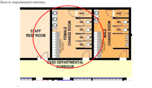
Activities
Shower
Grooming
Hand wash • Use of WC or urinal.
Requirements
- Secure storage of personal property is essential
- Staff to provide their own padlocks.
Fixtures, fittings and equipment
- Clothes lockers with bench
- Sanitary o Shower
- WC
- Hand-wash basins
- Hand-towel dispensers
- Soap dispenser
- Mirrors
- Toilet-roll holders.
Male change rooms
Function
Male toilet and change area.
Location and relationship
Outside the core activity area of the CSSD
Close to departmental entrance.
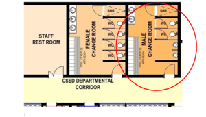
Activities
- Shower
- Grooming
- Hand wash
- Use of WC or urinal.
Requirements
- Secure storage of personal property is essential
- Staff to provide their own padlocks.
Fixtures, fittings and equipment
- Clothes lockers with bench
- Sanitary o Shower o Urinals
- WC
- Hand-wash basins
- Shoe racks
- Hand-towel dispensers
- Soap dispenser
- Mirrors
- Toilet-roll holders
- Laundry bag holders.
Steriliser plant room
Function
Service area of the sterilisers.
Location and relationship
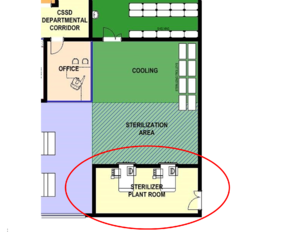
Activities
- Maintenance and repair of autoclaves by trained technical staff
- Sampling facilities for steam and water quality
- Limited access to trained skilled maintenance personnel only.
Requirements
- Technical personnel need to access the steriliser controls through the PPE room
- Waterproof, hardwearing floor, with a gradient in the direction of a floor drain
- Clearances as per specifications as steriliser manufacturers • Adequate space for maintenance and periodic testing is essential.
Access to the maintenance area of the autoclaves must not interfere with the CSSD activities. For singledoor autoclaves, there must be no connecting door between the maintenance area and the sterilised supply store. The maintenance area in particular should be well ventilated by natural means assisted by mechanical extraction if necessary. Note that this only achievable with single door autoclaves. Where double door autoclaves are used care must be taken to identify an access point from within the unit, which causes least disruption.
Fixtures, fittings and equipment
As per manufacturer’s specifications.
Services
As per manufacturer’s specifications.
Building and Services
Building components, materials and finishes
Floors
Carpet or similar soft flooring should be avoided.
Impermeable, non-slip floor covering is recommended. PVC welded sheet vinyl, coved up the wall, ensures a watertight, hygienic surface which will withstand daily cleaning.
Small-diameter coving puts undue stress on the floor vinyl and is prone to cracking over time. Largerdiameter coving has the added advantage that in certain cases it prevents trolley wheels from being pushed against the wall, acting as an added wall protection.
Walls
Walls should be washable, preferably cladded by welded sheet vinyl. Durable polyurethane wall finishes are rapidly appearing on the market and selected products could also be suitable in certain circumstances.
Walls should be adequately protected against damage by loose equipment and wheeled traffic by buffer rails and corner guards, which should be appropriately sited to reflect the specifications of trolleys in use. Protruding elements of different trolleys are of varying height. This should be considered in the selection of wall protection.
Ceilings
Suspended modular ceilings with inlay panels are not suitable.
A minimum below-ceiling height of 2 800mm is recommended. If ceilings are lower, precautions must be taken with respect to the arrangement and number of air vents as well as to the temperature of the air circulated. This below-ceiling height will have implications for the noise level prevailing within the CSSD.
Ceilings should be:
- washable, impermeable and non-porous
- sealed to prevent ingress of airborne particles or other contaminants from the ceiling void
- resistant to humidity in zones where steam and moisture may be encountered.
Windows
The walls and partitions must feature as many glass panels as possible to facilitate supervision, and also to create a feeling of spaciousness.
Windows to the outside are highly desirable in the working areas. However, these windows should be non-opening, sealed and preferably flush fitting, in order to prevent the windowsills from being used as storing space. If this is unavoidable, the sills should be angled.
Doors
Doorways should be positioned to allow trolley movement, and doors and corridors should be wide enough to accommodate trolley turning circles and protruding trolley fittings.
Door frames and door leaves should be designed and finished with protection cladding and bumper rails to withstand the inevitable bumps by trolleys.
Doors should be adequately sized to allow clear passage of current as well as possible future equipment.
Automatic/semi-automatic doors make it easier for collection and distribution of trolleys. If not automated doors should be self-closing. If the design allows it, doors should open towards the higher pressure side where possible to overcome problems with weakening door closers, which may lead to lock-outs.
Vision panels should be provided.
Hatches
Where hatches are required to accommodate transfer of articles between the decontamination area and IAP area, for example, they should have purpose-designed close-fitting sections to preserve the integrity of the ventilation system.
Ducts
Service ducts should:
- allow easy access and should ideally not be in the clean and sterile areas
- be protected as far as possible from unauthorised entry
- allow for eventual removal and replacement of major plant and equipment
- allow enough space to access equipment for cleaning or replacement.
Fixtures, Fittings and equipment
The selection of equipment should be fully coordinated with the facility’s design in order that utility and space requirements are considered during design development.
Sterile storage shelving
Packs should be stored away from direct sunlight and water and should not be stored next to or under sinks, or on the floor where they are likely to get wet or damaged. Sterile packs should be stored at least 250 mm above the floor, and 450mm below the ceiling or sprinkler heads and at least 50 mm from side walls to allow for air circulation in the room and to prevent contamination during cleaning. The shelves should be 400mm apart and be adjustable in increments of about 50mm.
Shelving should be stainless steel, slatted, 375mm deep, easily cleaned and allow air to circulate around stored packs. Freestanding or mobile shelving provides a practical solution for handling the flow of products in and out of storage and cleaning. It allows staff to access all sides of the storage area for rotation of sterile packs. Open shelving is more commonly used as it allows dust to pass through making them easier to clean than solid shelves.
Worktop furniture
Work benches for standing activities should have a worktop height of 900mm and be constructed of stainless steel. Furniture should be movable with height adaption facilities.
Hand-wash basins
Hand washing remains one of the most significant ways in which cross-infection through contact can be avoided. To enhance this, staff should be aware of its importance and hand-wash facilities should be available in appropriate places and be accessible.
The selected system for soap- and towel-dispensers is a hospital policy and dictates the type of dispenser to be specified.
Ultrasonic cleaners
Ultrasonic cleaners are mechanical pre cleaners and often used as an initial step in the process of cleaning surgical instruments. Ultrasonic cleaners are a mechanical system that uses sound waves along with water and detergent to remove soil from instruments. Both tabletop and floor units are available. Floor units are designed to accommodate large quantities of instruments at one time and can have either single or double chambers. Following the ultrasonic cleaning process, instruments are placed into washer/disinfectors. Instruments and trays are loaded into the unit on the decontamination side of the CSSD facility, and removed upon completion of the cycle on the clean side of the facility.
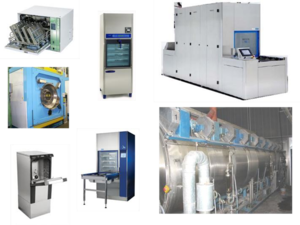
Automated washers / Washer-disinfectors
Washer-disinfectors are used to clean and disinfect a range of devices and materials that are intended to be re-used. The cleaning and disinfection process is intended to make the items clean but also safe (microbiologically) for staff to handle (as a prerequisite for packaging and sterilisation), reducing the load of microorganisms on device surfaces and also often for direct/indirect use with a patient (in particular non- and semi-critical devices).
There are many different sizes and types of washers. They may be single or multi-chamber, single (one) or double (two) door, and varying in size/design. In single-door designs, the devices or materials (referred to as the ‘load’) are introduced and removed from the same door, while double-door designs allow for the introduction and removal through separate doors (pass-through design). The pass-through door washers are preferable, as contaminated items can be loaded in the ‘dirty’ area and removed in the ‘clean’. The disadvantage of a single-door washer is that the contaminated and clean items are loaded and unloaded through the same door from the ‘dirty’ side.
Sterilisers (autoclaves)
For maintenance purposes, the side, back, and top panels of free-standing sterilisers should be easily removable and replaceable.
Special foundations are not normally required. The weight of the steriliser, which can be as much as 2 000kg when fully loaded, should be borne by at least four pads, each measuring at least 150 x 150mm. Floor mountings should be designed to minimise vibration.
A steriliser installation will normally be separated into two areas: a plant room containing the steriliser itself, services and ancillary equipment; and an adjacent loading area from which the steriliser is loaded and unloaded. The areas are divided by a partition wall into which the front panel and door of the steriliser are set.
Maintenance staff should be able to enter the plant room without passing through the loading area. Direct access between the plant room and loading area should be provided for use during testing. Page Break
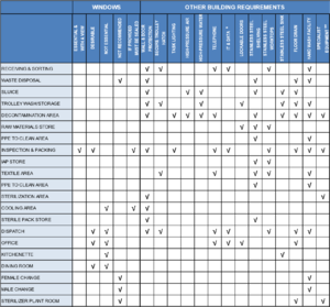
* IT & DATA IT & dta requirements as per hospital policies and procedures
** SPECIALIST EQUIPMENT Building services and environmental requirements as per manufacturer's specifications
Electrical
Specialist electrical installations
Rapid development of technological innovations in all spheres of electronic devices demands up-to-date knowledge which cannot be captured in a design guide of this nature.
It is therefore imperative that all power be fully accommodated, and that the systems are designed to be responsive to specific equipment. The specific choice of equipment must be established early on to promote a consistent and coordinated plan.
Careful attention must be given to the location and capacity of electric outlets to ensure capacity and compatibility with the equipment to be installed.
Electrical points
Sufficient 13-amp outlets should be provided to supply all portable appliances. Designers should ensure that they have access to a complete schedule of the equipment that requires electrical supplies and a clear understanding of the operational policies regarding the use of all equipment.
Switched socket-outlets should be provided in corridors and in individual rooms to enable domestic cleaning appliances to operate over the whole facility.
Appliances requiring a three-phase supply or those rated in excess of 13-amp single phase should be permanently connected to separate fused sub-circuits. The sub-circuits should be fed from the distribution board and terminate at a local isolator. Designers should agree on the location, type (flush- or surface-mounted), form of indication, type of cable outlet, facilities for locking of isolator in the off position, and labelling of such isolators with the planning team.
Lighting
The layout of artificial lighting should be designed in a modular fashion to accommodate future changes, yet take into consideration current workspace layout.
Light fittings are potentially major sources of dust- and dead-insect build-up. Recessed and sealed fittings utilising recessed fluorescent luminaries with acrylic prismatic lenses would greatly contribute to overcome this problem. However, regular maintenance policies still need to be put in place by hospital management to maintain a clean environment.
It would be preferable to have pendants above workspaces in the IAP area. Examination lighting (examination lamps with foot-operated switches) is required in the IAP (equipment examination) areas.
Light switches with occupancy sensors should be considered to reduce energy consumption.
Emergency lighting is not considered to be essential.
Table 9: Summary of lighting requirements
| RECOMMENDED LIGHTING LEVELS (lux) | |||
| minimum | average | maximum | |
| GENERAL INSPECTION | 500 | 750 | 1000 |
| DETAILED INSPECTION | 1000 | 1500 | 2000 |
| WASH AREAS | 500 | 750 | 1000 |
| GENERAL WORK AREAS | 200 | 300 | 500 |
| STORAGE AREAS | 200 | 300 | 500 |
Mechanical
HVAC
A well-designed HVAC system is a critical element in the design for infection control. Through constantspace airflows and differentiation in air pressures, contamination can be contained and clean environments can be maintained.
In order to achieve this it is imperative that 100% constant fresh air is provided to the CSSD through a dedicated air-handling unit complete with primary air heating, cooling, humidification, dehumidification, and filtration. The HVAC must be engineered with excellent energy efficiency through performance management. Refer to IUSS:GNS Building engineering services.
Air flow should be designed so that air flows out of clean areas into dirty areas via positive pressure. Positive air pressure is required in the "clean" areas of the unit to reduce air movements into these areas from the "dirty" areas of the unit, as per the diagram below.
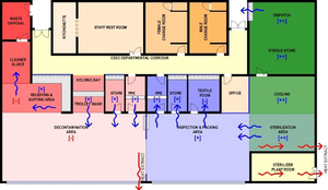
Table 10: Summary of environmental requirements
| ENVIRONMENTAL REQUIREMENTS | |||||
| Temp range
ᐤC |
Minimum air change per minute | Relative humidity | Comparative air pressure | Note | |
| RECEIVING & SORTING | 22 | + | |||
| WASTE DISPOSAL | 16-19 | DOOR TO SLUICE UNDERCUT | |||
| SLUICE | 22 | - - | |||
| TROLLEY WASH/STORAGE | 22 | + | |||
| DECONTAMINATION AREA | 22 | 10 | - | MECHANICAL HOT AIR EXTRACTION | |
| RAW MATERIALS STORE | 22 | + | |||
| PPE TO CLEAN AREA | 22 | + | |||
| INSPECTION & PACKING | 22 | 40-60 | + | ||
| IAP STORE | 22 | + | |||
| TEXTILE AREA | 22 | - | LINTING FILTER TO OUTSIDE | ||
| PPE TO CLEAN AREA | 22 | + | |||
| STERILIZATION AREA | 16-21 | 10 | ++ | MECHANICAL HOT AIR EXTRACTION | |
| COOLING AREA | 16-21 | 10 | 30-60 | ++ | |
| STERILE PACK STORE | 16-21 | 10 | ++ | ||
| DISPATCH | 22 | 10 | ++ | ||
| OFFICE | 22 | ||||
| KITCHENETTE | |||||
| DINING ROOM | |||||
| FEMALE CHANGE | |||||
| MALE CHANGE | |||||
| STERILIZER PLANT ROOM | MECHANICAL HOT AIR EXTRACTION | ||||
Building Services
Refer to IUSS:GNS Building engineering services
Plant and Services
The various areas within the CSSD should accommodate the equipment manufacturer's recommendations, as space requirements may vary from one manufacturer to another. All items of equipment will need to be itemised and the dimensions of all equipment obtained from manufacturers to ensure they can be suitably housed.
The following requirements could be relevant to washer/disinfectors and sterilisers:
- doors are to be sized to allow passage of equipment;
- electricity loads need to be estimated and catered for;
- weight loads need to be estimated and checked structurally;
- equipment requiring services such as water and special power need to be accommodated at an early stage;
- all sterilisers should be located to have service/maintenance access to equipment from outside the unit whenever possible;
- space allowed for and around equipment should be sufficient to allow for the physical equipment as well as circulation/working space around the equipment;
- the spaces should be able to reasonably accommodate access and positioning of possible outsize equipment, including point of delivery to point of positioning; and
- the area should be designed to allow for periodic ease of routine cleaning or, particularly in dirty areas, for handling of accidental spillages.
Definition of terms
Adventitious contamination:
The accidental introduction of environmental micro-organisms onto a medical device or product.
Anatomy:
The study of the structure of living things.
Antimicrobial:
The ability of a process or product to be effective against microorganisms by either killing them or inhibiting their growth.
Antisepsis:
Destruction or inhibition of microorganisms in or on living tissue, e.g. the skin, mucous membranes or wounds.
Antiseptic:
An antimicrobial product or process used on the skin or other living tissues. In some countries antiseptics are labelled as disinfectants or antiseptic disinfectants.
Asepsis/Aseptic:
Free of, or using methods to keep free of, microorganisms.
Bacteria:
Also known as eubacteria. A group of unicellular, prokaryotic microorganisms. Examples include Bacillus, Staphylococcus and Pseudomonas.
Biocide:
A general term referring to any chemical or physical antimicrobial agent that inhibits or inactivates life. The term ‘micro-biocide’ are those biocides that are effective against microorganisms. Chemical biocides include chlorine, iodine, alcohols and hydrogen peroxide. Physical biocides include heat and radiation.
Biofilm:
Communities of microorganisms (either singular or multiple species) developed on or associated with surfaces.
Carrier:
A device that carries, conveys or transports the load through the department via a trolley/carriage or on a rail/track into/through a decontamination process.
Cleaning chemistry:
A formulation (or mixture of chemicals) designed for cleaning purposes. Cleaning chemistries are often referred to as ‘detergents’, but detergents are usually only one part of these mixtures that can include biocides, enzymes, buffers, chelating agents and other components.
Circulation:
Circulation space is the space required within a department or unit to enable movement and functionality between individual rooms/ spaces.
Cleaning:
The removal of contamination (often referred to as ‘soil’) from a surface to the extent necessary for further processing (e.g., disinfection, sterilisation) or for intended use.
Contamination:
The presence of dirt or ‘soil’ that can include various materials, chemistries and bio burden (such as microorganisms). Depending on the situation, contamination may be visible (e.g., a blood spill) or invisible (e.g., the presence of microorganisms). Contamination of a device (e.g., an endoscope) following patient use is generally referred to as ‘soil’.
Decontamination:
Physical and/or chemical means to render a surface or item safe for handling, use or disposal. In many cases decontamination is at least a two- or even three-step process to include cleaning and disinfection and/or sterilisation; however, cleaning alone or a multi-step process of cleaning, disinfection and sterilisation may also be required for decontamination depending on the final use of the surface/item.
Detergent:
A compound, or a mixture of compounds, intended to assist cleaning. Detergents are a sub-class of surface active agents (‘surfactants’). Also commonly referred to as cleaners or cleaning chemistries, but detergents are only one part of these mixtures.
Device:
Any instrument, apparatus, appliance, material or other article intended to be used for the purpose of diagnosis, prevention, monitoring, treatment or alleviation of disease or other medical/surgical use. A reusable device is designed to be used many times on different patients, being provided with detailed instructions on how it can be safely reprocessed between each patient. A single-use device (SUD) has been designed by a manufacturer to be used on a single patient only and then discarded. The terms ‘device’ and ‘instrument’ are used interchangeably throughout the book.
Disinfectant:
A physical or chemical product for disinfection.
Disinfection:
The antimicrobial reduction of the number of viable microorganisms on a product or surface to a level previously specified as appropriate for its intended further handling or use. There are various levels of disinfection, based on their ability to kill certain types of microorganisms.
Facility:
A complex of buildings, structures, roads and associated equipment, such as a Hospital or Health Care Facility that represents a single management unit for financial, operational maintenance or other purposes.
Fixtures:
Items that are permanently fixed to the building or permanently connected to a service distribution system. These items require service connection (e.g. electrical, hydraulic, mechanical) and includes basins, light fittings, clocks, medical service panels, etc.
Fittings:
Refers to fixed items attached to walls, floors or ceilings that do not require service connections such as, hooks, mirrors, blinds, joinery, pinning and writing boards.
Fumigation:
The delivery of a disinfectant to an area by aerial dispersion, usually in the form of a gas, vapour or aerosol.
Fungi:
A group of cell wall containing eukaryotic microorganisms, that can be further sub-divided into moulds (or filamentous fungi, as they can form long filaments or lines of cells) and yeast (unicellular, single-celled forms).
Gross area:
Gross area includes, in addition to the net area, partitions and circulation internal to the functional area of the department.
Guideline:
Document used to communicate recommended procedures, processes, or usage of particular practices.
Infection:
The detrimental introduction and colonisation of a host (human/animal) by a microorganism.
Infection prevention/control:
Discipline concerned with preventing the spread of infection. Often used interchangeably, ‘prevention’ is more correctly used to describe practices to prevent infection while ‘control’ may also include practices to control the infection after it has taken place (e.g., isolation precautions, antibiotic or other drug-based therapy etc).
Label:
An identification indication on a product or other article. This can include the manufacturer, their address, product/item identification (e.g., serial or part number), instructions for use etc. A product label can include what is physically written on the product (the attached label) but also any other accessory information such as additional instructions for use, the material safety data sheets (MSDS) and technical literature.
Load:
Collectively, all the goods, equipment and materials that are put into a steriliser or washer/disinfector at any one time for the purpose of processing it.
Medical device:
Any instrument, apparatus, appliance, material or other article.
Mobile equipment:
Equipment items (medical or non-medical) that require electrical or mechanical connections or floor space.
Net area:
Net area is the actual floor area in a room or functional area (finish to finish) that can be used by people, furnishings, or equipment.
PPE (Personal Protective Equipment):
Specialised clothing or equipment worn by an employee for protection against a hazard.
Pressure:
The effect that occurs when a force is applied on a surface or the force applied per unit area. For example, atmospheric pressure is the pressure exerted by the earth’s atmosphere and which at sea level is known to be ~101.3kPa (=14.7 lb in-2, 1 bar, 760 mmHg or 760 Torr).
Process:
A designed sequence of operations or events, possibly taking up time, space, expertise or other resource, which produces some outcome.
Safety:
The condition of being protected from danger, harm or injury.
Soil:
See contamination.
Sterile:
Free from viable organisms.
Sterile barrier system :
Package that provides a barrier to microorganisms and allows aseptic presentation of product at the point of use.
Sterilisation:
Defined process used to render a surface or product free from viable organisms, including bacterial spores.
Tray:
A container, usually with a flat base and upturned edges, used for containing an assembly of surgical instruments for packing to be used in an aseptic procedure.
Validation:
Documented procedure for obtaining, recording and interpreting the results required to establish that a process will consistently yield product complying with predetermined specifications.
Virus:
A class of microorganisms that are unable to grow or reproduce outside a host cell.
Washer-disinfector:
A machine that cleans and disinfects medical devices and other articles used in the context of medical, dental and pharmaceutical practice.
References
American Institute of Architects, 2008. Principles and design considerations for sterile processes, Course number: get11a. [pdf] New York: Ron Blank and Associates Inc. Available at: http://www.ronblank.com/courses/get11a/get11a.pdf [Accessed 24 March 2014].
ANSI and Association for the Advancement of Medical Instrumentation (AAMI), 2011. ANSI/AAMI ST79:2010&A1:2010 & A2:2011 (Consolidated Text) Comprehensive guide to steam sterilization and sterility assurance in health care facilities. Arlington: AAMI.
Bartley, J.M., Olmsted, R.N. and Haas, J., 2010. Current views of health care design and construction: Practical implications for safer, cleaner environments. American Journal of Infection Control, 38(5).
Centre for Healthcare Related Infection Surveillance and Prevention (CHRISP), 2006. Disinfection & sterilization: Infection control guidelines. (Section 1 and 2). Queensland: CHRISP.
Department of Veterans Affairs, 2010. Design guide: Supply processing & distribution. Washington: DVA.
French Sterilisation Association (AFS), 2008a. (Central service volume 16 pp. 196-204). Architecture and sterilisation premises. [pdf] France: AFS. Available at:
http://www.wfhss.com/html/educ/recommendations/afs-recommendation-001_en.pdf [Accessed 24 March 2014].
French Sterilisation Association (AFS), 2008b. (Central service volume 16 pp. 281-293). Architecture and sterilisation premises-Part 2. [pdf] France: AFS. Available at:
http://www.wfhss.com/html/educ/recommendations/afs-recommendation-001_en.pdf [Accessed 24 March 2014].
Health Authority Abu Dhabi (HAAD), 2011. Sterile supply unit (SSU). (Part B- Version 3.1) [pdf] Abu Dhabi: HAAD. Available at: http://www.healthdesign.com.au/haad.hfg/full_index/haad_b_sterile_supply_unit.pdf [Accessed 24 March 2014].
McDonnell, G. and Sheard, D., 2012. A practical guide to decontamination in healthcare. United Kingdom :Wiley-Blackwell.
NHS Estates, 1995. Health Technical Memorandum (HTM) 2010: Sterilization – Part 2: Design considerations. London: HMSO.
NHS Estates, 2004. HBN 13 Sterile services department. Norwich: The Stationery Office.
Nuffield Provincial Hospitals Trust, 1963. Central sterile supply: Principles and practice. London: The Oxford University Press.
Putsep, E. and Cowan, D., 1983. A design guide to sterilised and disinfected supplies in hospitals. Pretoria: Council for Scientific and Industrial Research.
Seavey, R., 2008. Designing a new sterile processing department. Healthcare Purchasing News, [online] Available at: http://www.hpnonline.com/ce/pdfs/0806cetest.pdf [Accessed 24 March 2014].
Sheard, D., 2013. CSSD designed for optimum output. In: Africa Health, Decontamiation and sterilisation. Gallagher Convention Center, Midrand, Johannesburg, South Africa, 7-9 May 2013. South Africa: Africa Health.
Annexure 1: CSSD forum standard operating procedure sterile service departments
| SOP No 1 | Safety Awareness in Sterile Service Department |
| SOP No 2 | Department Cleaning Procedure |
| SOP No 3 | Departmental Dress Code |
| SOP No 4 | Collection of Soiled/Contaminated Equipment |
| SOP No 5 | Manual Decontamination of Medical Devices |
| SOP No 6 | Prepare, Load and Operate Decontamination Equipment |
| SOP No 7 | Decontamination and Inspection of Loaner Medical Devices |
| SOP No 8 | Cleaning and Maintenance of Rigid Containers |
| SOP No 9 | Missing Instruments |
| SOP No 10 | Control of Packing Area |
| SOP No 11 | Packing Area Operation |
| SOP No 12 | Packing of Loaner Sets |
| SOP No 13 | Cleaning of Autoclaves |
| SOP No 14 | Steam Sterilisation Procedure |
| SOP No 15 | Ethylene Oxide Sterilisation |
| SOP No 16 | Loading and Unloading Items from the Autoclave |
| SOP No 17 | Sterile Pack Storage |
| SOP No 18 | The Delivery and Distribution of Processed items |
| SOP No 19 | Monitoring |
| SOP No 20 | Monitoring Autoclaves |
| SOP No 21 | Traceability and Recall Procedures |
| SOP No 22 | Validation of Equipment |
| SOP No 23 | Monitoring ETO Steriliser |
| SOP No 24 | Malfunction of Ethylene Oxide Steriliser |
| SOP No 25 | Planned Maintenance Schedule of Equipment |
| SOP No 26 | Acton for Breakdown of Equipment |
| SOP No 27 | Sterile Packaging |
| SOP No 28 | Quality Management |
| SOP No 29 | Decontamination of Textiles/Linen for Sterilisation |
| SOP No 30 | Inspection, Repair and Replacement of Instruments |
| SOP No 31 | Checking, Assembling and Packing (Wrapping) an Instrument Set |
| SOP No 32 | Prepare, Load and Operate Ultrasonic Cleaner |
| SOP No 33 | Low Temperature Sterilisation (Hydrogen Peroxide Plasma / Vaporised Hydrogen Peroxide) |
| SOP No 34 | Decontamination and Management of Laryngoscopes |
| SOP No 35 | Daily Heat-Sealer Checks |
| SOP No 36 | Decontamination and Disinfection of Babies Bottles |
| SOP No 37 | Decontamination and Sterilisation of Reusable LMAs |
Annexure 2: South African Legislation and guidelines
International Organisation for Standardisation (ISO), 2005. ISO 14644-3 Cleanrooms and associated controlled environments - Part 3: Test methods. Switzerland: ISO.
South African Bureau of Standards (SABS), 1990. SANS 10400:1990 Code of practice for the application of the national building regulations. Pretoria South Africa: SABS Standards Division.
South African Bureau of Standards (SABS), 1993. SANS 10252-2:1993 Water supply and drainage for buildings Part 2: Drainage installations for buildings. Pretoria South Africa: SABS Standards Division
South African Bureau of Standards (SABS), 1999. SANS 14644-1:1999 Cleanrooms and associated controlled environments Part 1: Classification of air cleanliness. Pretoria South Africa: SABS Standards Division.
South African Bureau of Standards (SABS), 2003. SANS 10173:2003 The installation, testing and balancing of air-conditioning ductwork. Pretoria South Africa: SABS Standards Division.
South African Bureau of Standards (SABS), 2003. SANS 14644-2:2003 Cleanrooms and associated controlled environments - part 2: Specifications for testing and monitoring to prove continued compliance with ISO 14644-1. Pretoria South Africa: SABS Standards Division.
South African Bureau of Standards (SABS), 2005. SANS 10114-1:2005 Interior lighting Part 1: Artificial lighting of interiors. Pretoria South Africa: SABS Standards Division.
South African Bureau of Standards (SABS), 2005. SANS 1238:2005 Air-conditioning ductwork. Pretoria South Africa: SABS Standards Division.
South African Bureau of Standards (SABS), 2009. SANS 10142-1:2008 The wiring of premises part 1: Lowvoltage installations. Pretoria South Africa: SABS Standards Division
South African Bureau of Standards (SABS), 2009. SANS 10147:2009 Refrigerating systems including plants associated with air-conditioning systems. Pretoria South Africa: SABS Standards Division.
South African Bureau of Standards (SABS), 2009. SANS 40:2009 Manually operated medium-vacuum sterilizers (autoclaves). Pretoria South Africa: SABS Standards Division
South African Bureau of Standards (SABS), 2009. SANS 7396-1:2009 Medical gas pipeline systems Part 1: Pipeline systems for compressed medical gases and vacuum. Pretoria South Africa: SABS Standards Division.
South African Bureau of Standards (SABS), 2009. SANS 981:2009 High-pressure down-draught steam sterilizers (autoclaves) (with independent steam supply). Pretoria South Africa: SABS Standards Division
South African Bureau of Standards (SABS), 2009. SANS 982:2009 High-pressure high-vacuum steam sterilizers (autoclaves). Pretoria South Africa: SABS Standards Division
South African Bureau of Standards (SABS), 2010. SANS 50868-10:2010 Packaging for terminally sterilized medical devices Part 10: Adhesive coated nonwoven materials of polyolefines- Requirements and test methods. Pretoria South Africa: SABS Standards Division.
South African Bureau of Standards (SABS), 2010. SANS 50868-9:2010 Packaging for terminally sterilized medical devices Part 9: Uncoated nonwoven materials of polyolefines- Requirements and test methods. Pretoria South Africa: SABS Standards Division.
South African Bureau of Standards (SABS), 2011. SANS 1453:2011 Copper tubes for medical gas and vacuum services. Pretoria South Africa: SABS Standards Division.
South African Bureau of Standards (SABS), 2012. SANS 10252-1:2012 Water supply and drainage for buildings part 1: Water supply installations for buildings. Pretoria South Africa: SABS Standards Division
South African Bureau of Standards (SABS), 2012. SANS 1091:2012 National colour standard. Pretoria South Africa: SABS Standards Division.
South African Bureau of Standards (SABS), 2013. SANS 1424:2013 Filters for use in air-conditioning and general ventilation. Pretoria South Africa: SABS Standards Division.
South African Bureau of Standards (SABS), 2013. SANS 62040-1:2013 Uninterruptible power systems (UPS) Part 1: General and safety requirements for UPS. Pretoria South Africa: SABS Standards Division.
The Occupational Health and Safety Act 1993. (c.85). Cape Town South Africa: Government Gazette.
Please help to expand this page. |